

I finished the first version of the Anti-Gravity Device in 1975 and it sat on my various workbenches for 35 years. In 2010 I decided to take to the next step.
Once I had the proper tools, a reasonable size lathe and Bridgeport mill, continuing the project was feasible.
It would take another 2 years to take this project from start to testing the theory with 20 of my friends and family as witnesses.
Does it work, not yet. The torque of the machine broke some key welds and pulled loose a number of counter weights, but I’m not finished with this project.
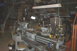
The lathe was made in 1954 in Communist Russia long before cheap China knock-off’s. How it got over to the USA, I do not know.
What a great machine. Still accurate after all of these years.
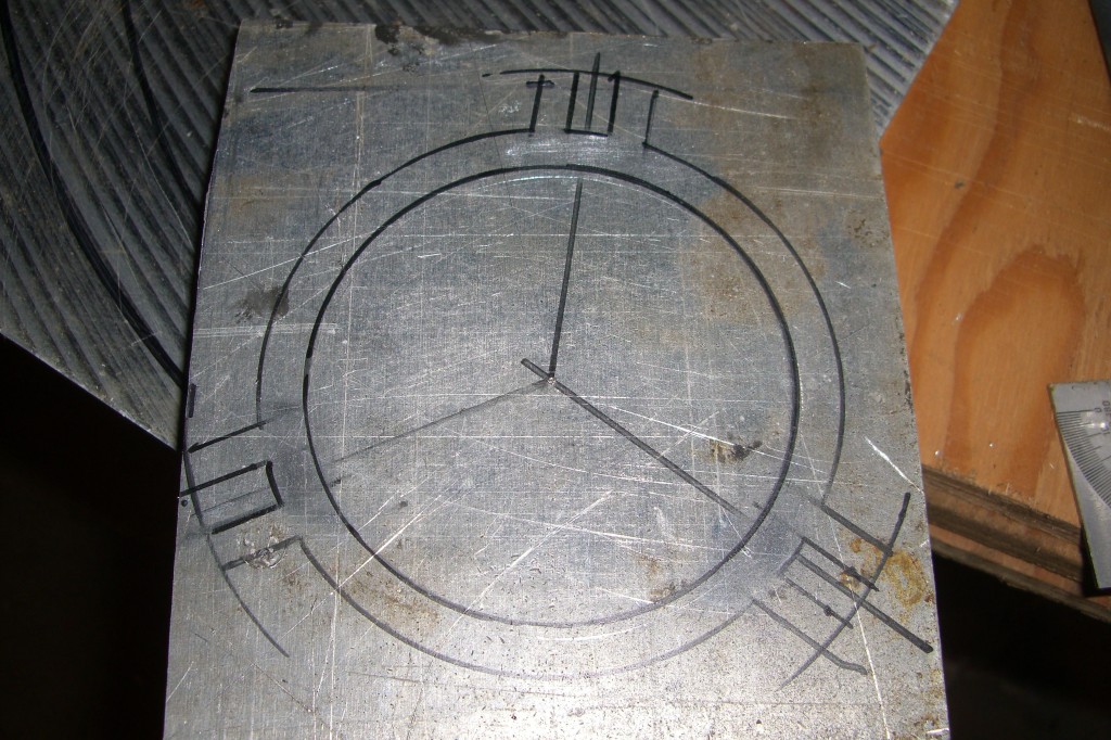
I began with a 2 foot square piece of aluminum, laid out the pattern and began cutting the shape with my Bridgeport mill.
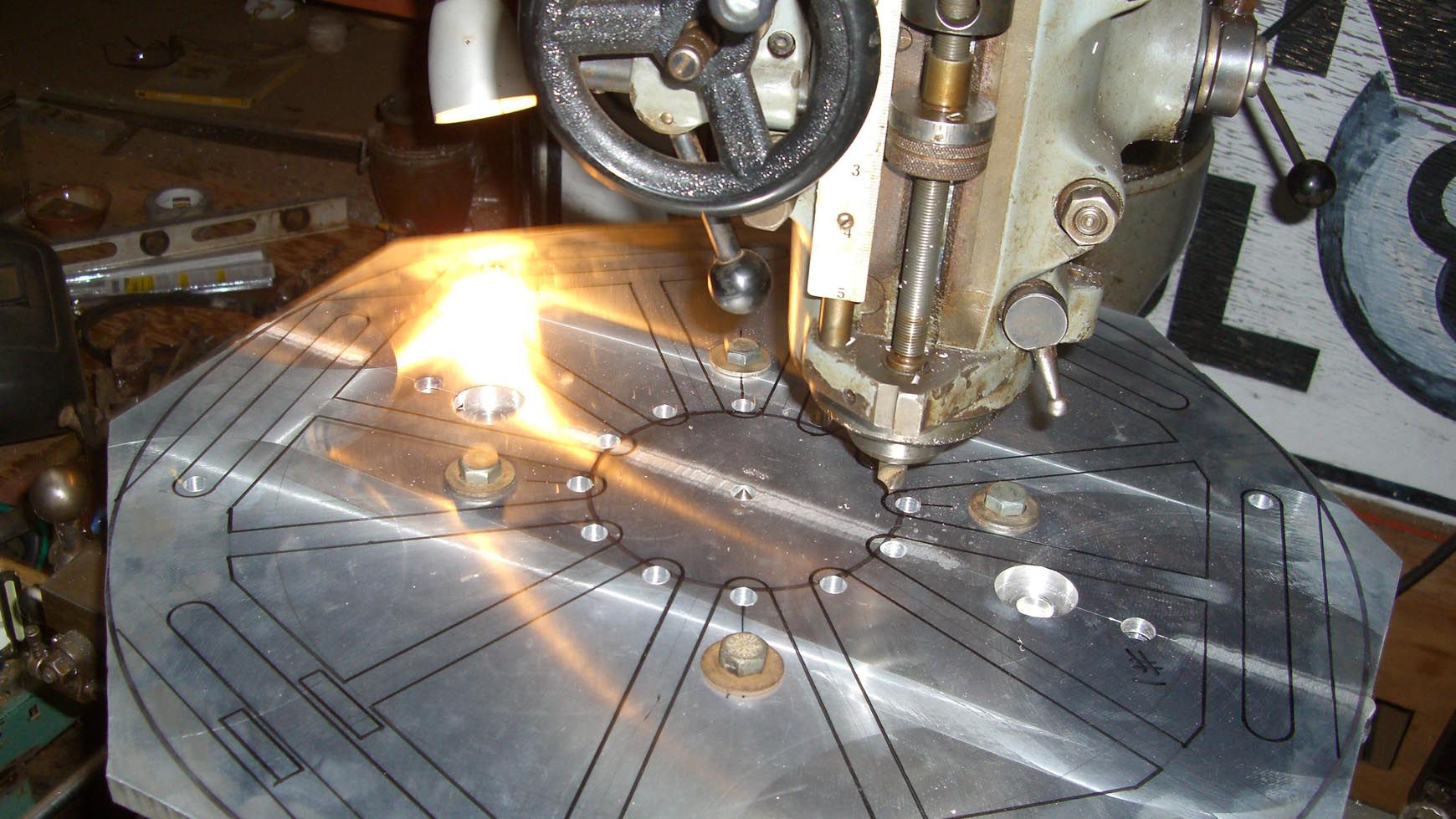
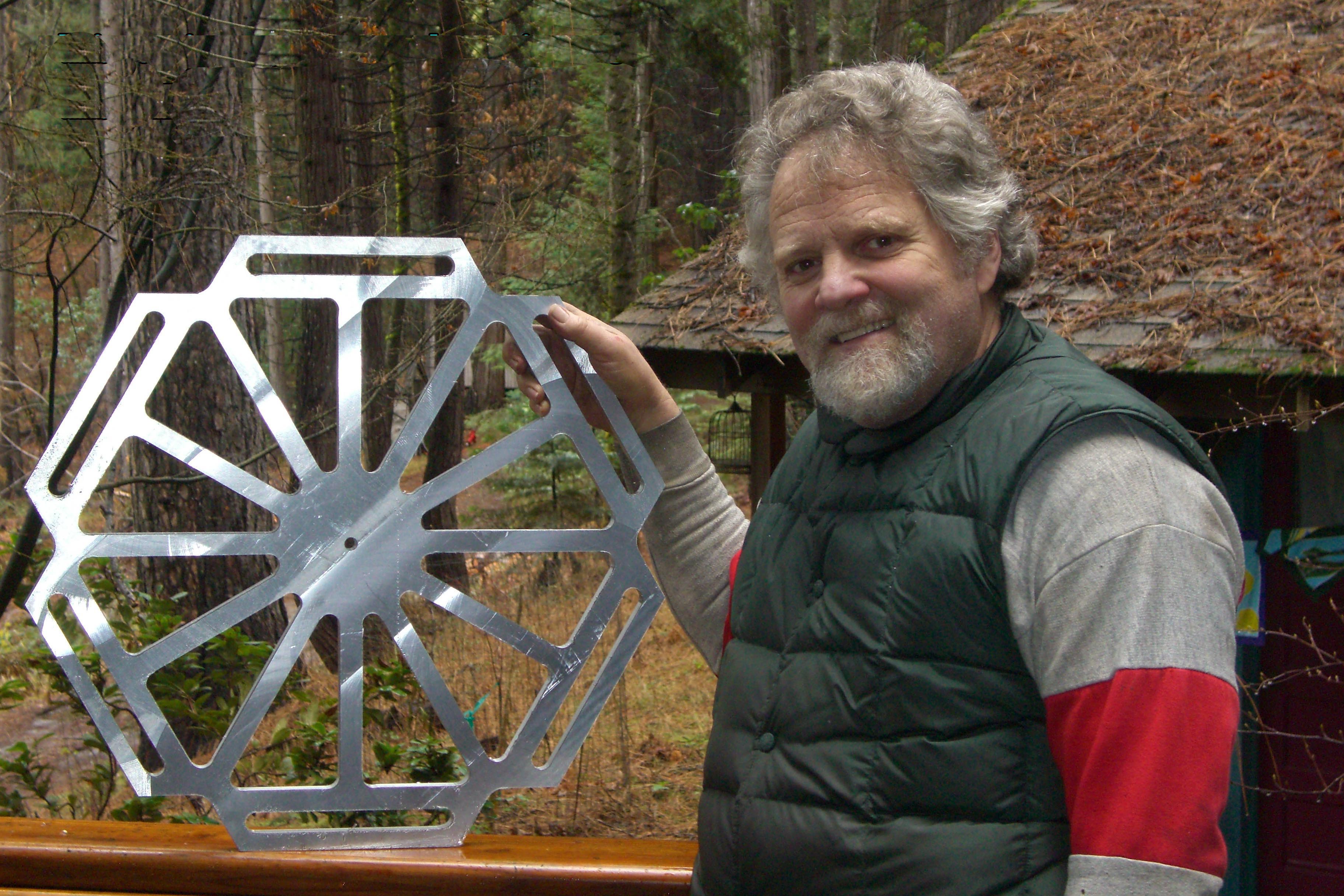
A week later the platform was complete.
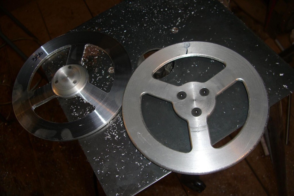
 A few weeks later the six small wheels were finished.
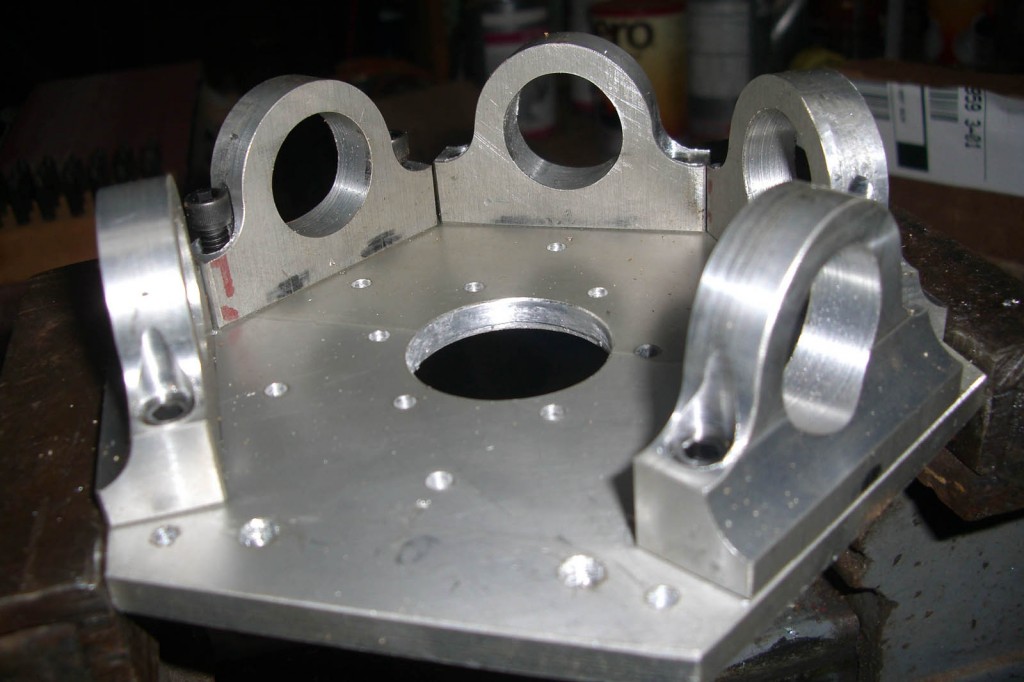
The bearing blocks needed a complicated 14 step process to not only finish them with precision, but to reproduce each of the moves 18 times. It took a fun two weeks to complete. There is something about being accurate to a thousandths of an inch that matches with my personality.

Next, I needed to build an inner circle 1/4 inch higher to match the outer bearing block location and as a motor mount.
Closeup of the gears in place. 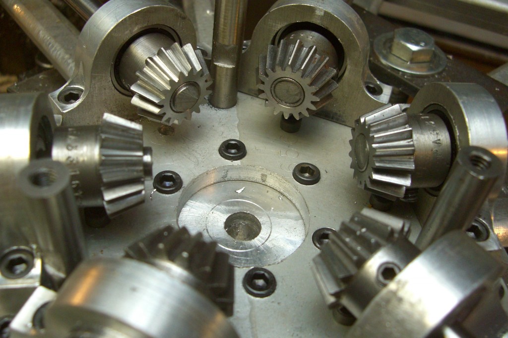
No, I didn’t machine the beveled gears. I bought them so cheaply it wasn’t worth the effort.
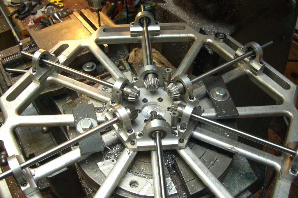
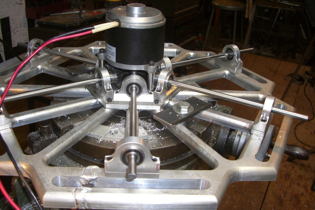
Below is an expanded view of the gears, drive shafts with bearings in place.
Now, let’s drop in the 24 volt DC upper motor to drive the smaller wheels.
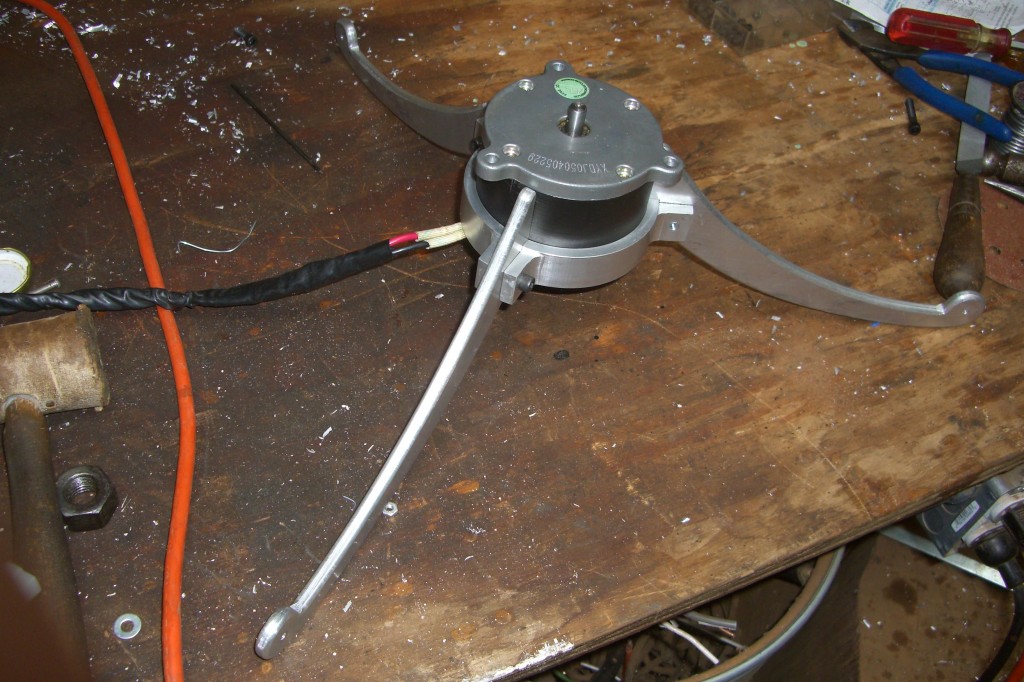
The entire machine will need to rest on the single shaft of the bottom motor, so I laid out a bracket on a 3/4″ thick piece of aluminum.
and machined the mounting bracket.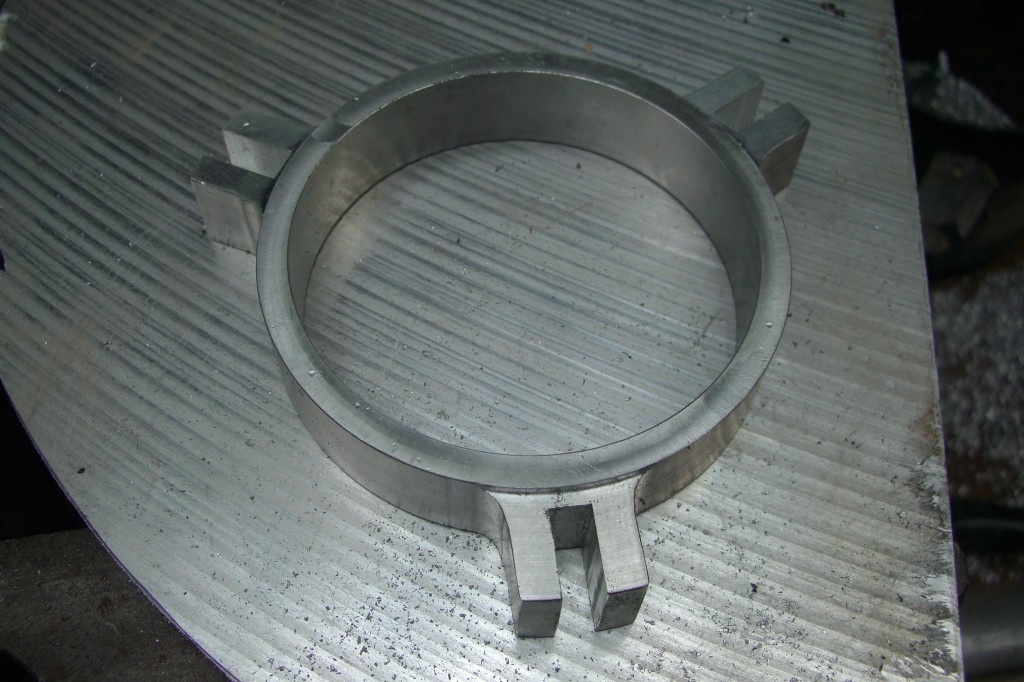
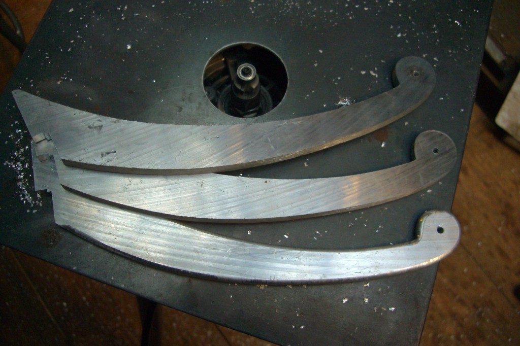
Next came the legs from 1/4″ aluminum.
Once assembled here is the stand with lower motor in place.
 Platform installed on lower motor with counter torque wheels in place.
outer bearings are not yet installed.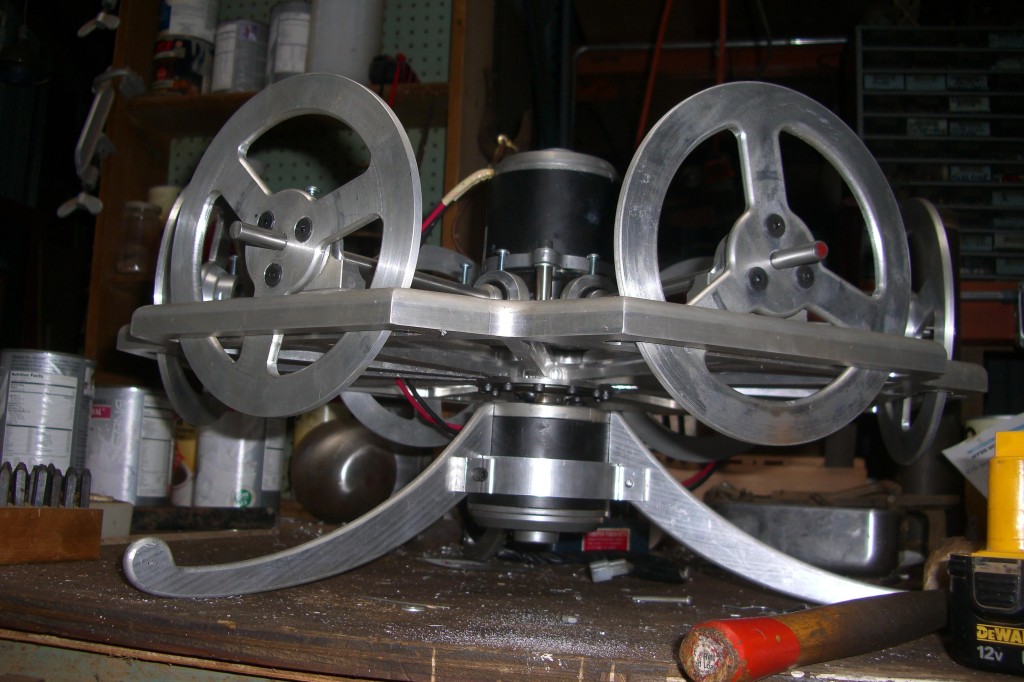
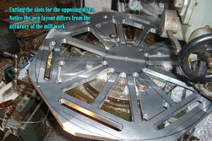
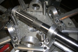 To get the bearings to align up with one another I needed to line bore the 3 bearings in place with each other using the bearings opposite as guides. Very complicated.
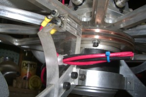
Next came the complicated process of transferring electricity from a static location through the spinning platform to the six counter torque wheels. After almost a month I completed this carbon brush design similar to a DC motor.
I invited 20 friends and family to witness the test in a driveway with 5 sheets of plywood surrounding the test site for safety. A boy is looking on as I tweaked the machine to get it to perform at optimum speed.

We got it spinning at a few thousand RPM, but once it broke two critical welds and threw four counter weights hitting Jon in the chest I shut down the test and now I’m back to the drawing board to make each component lighter weight and stronger.